
Assemble Pico 20H RockPro64
These instructions show how to assemble a complete Pico 20H ProckPro64 cluster.
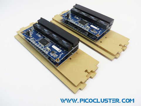
The instructions for assembling the RockPro64 5 board stack are here. You'll need 4 of these stacks to be completed before assembling the rest of the Cube.
Please contact support@picocluster.com if you encounter any difficulties.
Step 1 – Switch Panels
Remove the paper backing from the switch panels and open the switch package.
Screw the 3/4" M/F standoff through the switch board to the 1/2" F/F standoff on the other side of the switch. Attach the second switch to the the first using the other 3/4" M/F standoffs as shown. Attach the acrylic switch panels using the 3/8" screw and washers. Make sure the orientation is correct. The nut capture slots are at the bottom switch port. The switch power ports are at the top, opposite the nut capture slots. The front of the switch should stick out a bit from the acrylic panels when assembled properly. This needs to be done twice to form 2 switch assemblies.
Attach the switch assemblies to the base panel as shown. Use a screw/washer/nut combo from packet E. It's usually easier to place the nuts in the nut capture slots in the switch assembly, then set the assembly into the base panel, then insert and tighten screws from the bottom.
Place the switch assembly into place in the cluster as shown, then add the switch side panel and screw the switch assemble to the side panel using the 3/8" screws and nylon washers.


Step 2 – Base Panel
Remove the paper backing from the acrylic and screw the board stack to the base panel using the 3/8" screws and washers from packet A. The board stack goes on the upper right of the base panel with the micro SD card slots to the outside.


Step 3 – Network Wiring
Connect the network cables from each switch to one of the board stacks as shown. Each pair of switches needs to be cross connected to each other at the bottom using one of the network cables. The opposite stacks of switches will also need to be cross connected.


Step 4 – Power Supply and Wiring
Attach the leads for the boards to the left most terminals. They are from left to right [+ positive] [- ground].
Mount 2 power supplies to each side panel using the power supply screws and nylon washers from packet F.
Cross connect the A/C terminals on both power supplies as shown. They are from right to left [L power] [N neutral] [G ground].
Mount the A/C power connector using the 1/2" screws, nylon washers, and nuts from packet F and plug the A/C power input wires to the right most power supply terminals. They are from right to left [L power] [N neutral] [G ground]. Wire 2 of the power supplies, 1 on each panel closest to the power input receptacle the same way.


Step 5 – Back Panel and Fans
Attach the A/C power input wires to the right most power supply terminals. They are from right to left [L power] [N neutral] [G ground].
Attach the pre-wired leads for the board power and fans to the left most terminals. They are from left to right [+ positive] [- ground].
Attach the fans to the back and then front panels.
Attach the back panel to the base panel and side panels as shown. Use a screw/washer/nut combo from packet E.


Step 6 – Front Panel, Power Supply and Wiring
The front panel is laid out very similar to the back panel with a power supply and wiring.
Remove the paper backing from the front panel. Attach the HDMI and Ethernet extension cables to the front panel using the 3/8" screws and nylon washers from Packet D.
Press the power switch through the square hole as shone. The tabs on the top and bottom may need to be compressed.
Attach the switch front panel to the base panel and side panels as shown. Use a screw/washer/nut combo from packet E.


Step 7 – Internal Wiring
Plug the power cables from the power supply to each board as shown. Cabling can be zip tied together as desired.


Step 8 – Side Panels
Remove the paper backing from the acrylic and attach the both side panels to the base panel as shown. Use a screw/washer/nut combo from packet E for each panel.


Step 9 – Top Panel
Remove the paper backing from the acrylic and attach the top panel to the base panel as shown. Use a screw/washer/nut combo from packet E.


Step 10 – Completed Cube
Put formatted micro SD cards in each boards, turn on, connect to WAN network and enjoy!
