
Assemble Pico 10H Jetson Nano
These instructions show how to assemble a complete Pico 10H Jetson Nano cluster.
Please contact support@picocluster.com if you encounter any difficulties.
Step 1 – Base Panel
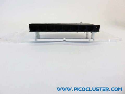
Remove the paper backing from the acrylic and screw the stack to the base panel using the 3/8" screws and washers from packet A. The board stack are mounted to the base panel as shown.
The jumpers go on the top, left front of each board. This allows the board to be powered from the barrel connector on the left side of the board.


Step 2 – Center Switch and PDU Panel
Attach a switch and PDU to the center panel as shown using screws from packets B and C.
Attach the center panel to the bottom panel using the 1/2" screw, nut and nylon washer from packet C as shown. The nut is placed in the nut capture slot in the center panel, then carefully placed into the slots on the bottom panel. The washer is placed on the screw and then inserted into the bottom panel and into the nut in the center panel. Tighten to snug, but don't over tighten.


Step 3 – Power Supply Wiring
Attach the A/C power input wires to the right most power supply terminals. They are from right to left [L power] [N neutral] [G ground].
Attach the black/red pdu cabling to the Power supply output screws labeled [+] and [-]. Attach the red wire to [+] and the black wire to [-] Make sure the terminals are screwed down tight.
Use cable ties to bind the cabling together.


Step 4 – Back Panel and Wiring
Attach the back panel to the base panel and side panels as shown. Use a screw/washer/nut combo from packet E.
Attach the fans using the #6 3/4" screws, nylon washers and nuts from packet F.
Mount the power supply to the back panel with the power supply screws and nylon washers from packet F.
Mount the A/C power connector using the 1/2" screws, nylon washers, and nuts from packet F.
Make sure that the A/C power connector is wired as shown.


Step 5 – PDU Side Panel
Remove the paper backing from the PDU side panel. Attach the PDU to the side panel as shown using the 1/2" screws, 1/8" nylon spacers, nuts and nylon washers. The washers go next to the acrylic on the outside.
Add the cabling as shown. The right-angle which power cable attaches to the right screw terminals, black [-] center and red [+5V] right.
Attach the PDU side panel to the base panel as shown. Use a screw/washer/nut combo from packet E.
Attach the fan plugs to the PDU fan connectors.


Step 6 – Switch Side Panel
Remove the paper backing from the switch side panel and open the switch package. Place the nylon washer on the 1" screws from packet C then thread through panel as shown. Place the switch onto the screws then tighten down with the nuts.
Plug the switch power cable into the power port on the switch using the 5.5mm barrel cable.
Attach the switch side panel to the base panel as shown. Use a screw/washer/nut combo from packet E.


Step 7 – Front Panel
Remove the paper backing from the front panel. Attach the HDMI extension cable to the front panel using the 3/8" screws and nylon washers from Packet D.
Press the power switch through the square hole as shone. The tabs on the top and bottom may need to be compressed.
Attach the switch front panel to the base panel and side panels as shown. Use a screw/washer/nut combo from packet E.

Step 8 – Cabling
Plug the HDMI cable to the HDMI port on the top board, then tuck the excess under the bottom board.
Plug the Ethernet cables from the boards into the network switch.
Plug the A/C power wiring to the front panel switch as shown. They may be Red/Blue/Yellow or Red/Black/White.

Step 9 – Top Panel
Remove the paper backing from the acrylic and attach the top panel to the base panel as shown. Use a screw/washer/nut combo from packet E.

Step 10 – Completed Cube
Put formatted micro SD cards in each boards, turn on, connect to WAN network and enjoy!
